Shelly 1 is a small size WiFi connected relay for controlling electrical appliances. The engineers from Alterco Robotics managed to fit the electronics in a nice enclosure with size of 4.1cm x 3.6cm, which allows the module to be installed in a wall switch console.
Specifications:
- ESP8266ex with 2mb of SPI flash
- 16A relay
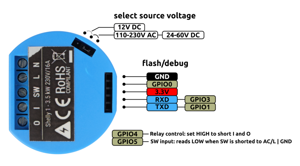
- Power source can be 12V DC, 24v-60v DC and 110-230AC
- Switch input
| Type | Shelly1 | Sonoff Basic |
|---|---|---|
| Size | 41 x 36 x 17 mm | 88 x 38 x 23 mm |
| Max current | 16A | 10A |
| Power Supply Voltage | DC: 12V, 24-60V AC: 110V-230V | AC: 90V-250V |
Shelly 1 is aimed at DIY enthusiasts who prefer to flash their own code to the smart devices. The engineers have placed a header with TX, RX, 3v3, GND and GPIO 0 pins thanks to which, we can flash the embedded MCU with our own code.
In the following lines I will guide you through the process of flashing the ESP8266 MCU with ESPEasy firmware.
ESPEasy is a nice firmware for the ESP8266 which allows us to program the MCU without writing a single line of code. It has a good looking web interface where all the configuration is done.
Required materials:
- Shelly 1
- USB to UART convertor
- Breadboard(recommended)
- Jumper wires
Steps for flashing the MCU:
- Download ESPEasy firmware
- Connect Shelly 1 with the USB to UART convertor following the pinout diagram below.
 In order to boot the ESP in flash mode GPIO 0 must be connected to GND when powering on the device. In this case I am using a breadboard and the orange jumper is connecting GPIO 0 and GND. After powering on the device we can remove the jumper between GPIO 0 and GND.
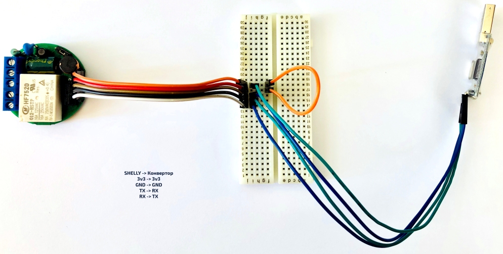
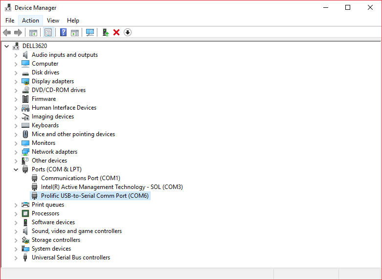
- Check on which COM port is the USB to UART convertor
- Start ESPEasy Flasher
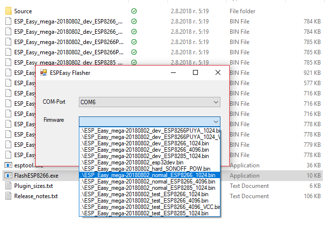 Choose the COM port on which the convertor is connected and select the normal_ESP8266_1024.bin file from the Firmware drop-down menu. Since the ESP in Shelly 1 has 2mb of flash we choose the firmware for 1mb flash.Press the flash button and wait for the firmware to upload.
 - Setup Wifi
After we have successfully flashed the ESP, it will make a WiFi hotspot with SSID ESP_Easy_0 and password configesp. The web interface is accessible on 192.168.4.1. More information here.
Add to Domoticz
From the web interface go to Controllers section to add a new controller. From the drop-down menu select Domoticz MQTt.
We fill in only the following fields:
- In Controller IP we fill in the IP address of the MQTT broker.
- In Controller port we fill in 1883
- In Controller User and Controller Password we fill in the credentials for the MQTT broker ONLY IF WE HAVE CREATED ONE! If not leave blank.
Put a tick on Enabled and click submit.
The only thing left is to add the Shelly’s relay and switch input as devices in the Devices section.
In Devices section we add all sensors and actuators that are connected to the ESP. In our case we have to add two records – one for the relay on GPIO 4 and one for the switch input on GPIO 5. For the relay we choose device type “Output – Domoticz MQTT Helper” and for the switch “Switch Input – Switch”. Fill in the fields as shown below and for IDX fill in the IDX of the virtual devices that you have created in Domoticz. Click on Enabled on both devices and also click on Send to Controller on the Switch settings.
